
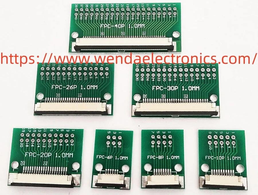
Modern electronic products often contain several printed circuit boards that perform different tasks within the same enclosure. One board may manage user inputs, another may process signals, and a separate assembly may support power distribution or communication. A Board to Board Connector provides a direct interface between circuit boards, helping designers organize these connections while managing internal space and assembly requirements. Its role extends beyond joining two boards physically: contact reliability, alignment, structural support, and compatibility with the surrounding electronics all influence the performance of the completed assembly. Evaluating these factors early can help product teams develop layouts that are practical to manufacture and maintain.
Material choices influence the electrical and mechanical characteristics of a board-level interface. Conductive contacts are commonly formed from copper alloys or other suitable conductive metals, selected according to their contact behavior, strength, and manufacturability. Surface finishes may help manage oxidation, wear, and contact stability, depending on the intended operating environment. Insulating housings are typically made from engineering polymers that separate conductive elements and maintain their relative positions. The printed circuit boards themselves also matter because their surface finishes, mounting areas, and structural characteristics must accommodate the selected connector. In some applications, additional shielding or protective features may be relevant to the surrounding design. Reviewing these materials as part of a complete assembly helps engineers avoid focusing on conductivity alone while overlooking insulation, mechanical integrity, and environmental compatibility.
Choosing a suitable connector begins with understanding the relationship between the boards being joined. Designers should identify how the boards are positioned, whether they connect face-to-face or in another arrangement, and how much flexibility the assembly process allows during mating. The available enclosure space, component placement, board support, and access for inspection can influence the appropriate connector style. Buyers should also consider whether the connection is intended to remain undisturbed or may need to be separated during maintenance. Electrical requirements, signal characteristics, power distribution needs, and the surrounding operating environment should be reviewed together. Comparing product drawings and checking the compatibility of mating components helps establish whether a proposed connector fits the intended layout rather than simply matching a general product description.
The technical operation of a board-level connection depends on the coordinated behavior of its contacts, housing, and mounting arrangement. Conductive contacts create the electrical paths between the respective circuit boards, while the insulating structure helps maintain separation and positioning. Depending on the design, alignment features can guide the boards into the correct mating position, reducing the likelihood of uneven engagement. The connector must also accommodate the mechanical conditions of the assembly without transferring unnecessary stress to solder joints or nearby components. Board support and enclosure design are particularly relevant when the connected boards may experience movement or vibration. Careful coordination between the connector, board layout, and supporting structure helps protect the interface and preserve electrical continuity during normal operation.
Manufacturing quality affects how consistently the connector can be integrated into electronic products. Contact forming and surface finishing must produce the intended conductive interfaces, while housing molding must maintain the geometry needed for reliable mating. During board assembly, the connector's mounting arrangement must align with the production process and the design of the printed circuit board. Inspection can reveal issues such as displaced contacts, housing defects, contamination, or inconsistent solder connections. Prototype assembly provides an opportunity to evaluate how easily the boards mate and whether the connector introduces interference with nearby components. Collaboration between connector suppliers, circuit designers, and manufacturing teams can identify potential problems before they become recurring production issues.
The experience of assembly technicians and maintenance personnel is shaped by the accessibility and predictability of the connection. Clear alignment features can make board positioning easier, while a connector that fits naturally into the assembly sequence can reduce unnecessary handling. When servicing requires board removal, the connection should be accessible enough to permit controlled separation without damaging adjacent components. Technicians also benefit from layouts that leave room for inspection and make it easier to identify the relevant interface. In automated production, connector placement and consistent orientation may affect how boards are positioned and handled by assembly equipment. These practical details influence manufacturing efficiency as well as the convenience of later repair and replacement.
Physical design determines how the connector fits into the overall electronic architecture. A compact housing may help preserve space for processors, sensors, shielding, and other circuit components, while the connector's orientation influences how boards are stacked or arranged within the enclosure. The mating direction can affect both assembly access and the routing of nearby cables. Housing shape and mounting features should also support the required mechanical stability without obstructing other components. For products with modular internal structures, an appropriately selected interface can help separate functional sections while keeping their electrical relationship organized. Visual appearance is less important than electrical and mechanical suitability, but a clean, consistent arrangement can make the assembly easier to understand during manufacturing and service.
Zhejiang Wenda Electronics Co., Ltd. provides electronic connection products for businesses developing circuit-based equipment and integrated electronic assemblies. When evaluating a board-level connection solution, product teams can share their board layout, mating arrangement, assembly method, and operating conditions to help clarify the relevant design priorities. Reviewing drawings and samples with the supplier can support compatibility checks and identify practical integration concerns before production planning progresses. Further information about the company's electronic components and connection solutions is available at https://www.wendaelectronics.com.

 English
 Arabic
 French
 Spanish
 Portuguese
 Deutsch
 Turkish
 Dutch
 Italiano
 Russian
 Romaian
 Portuguese (Brazil)