
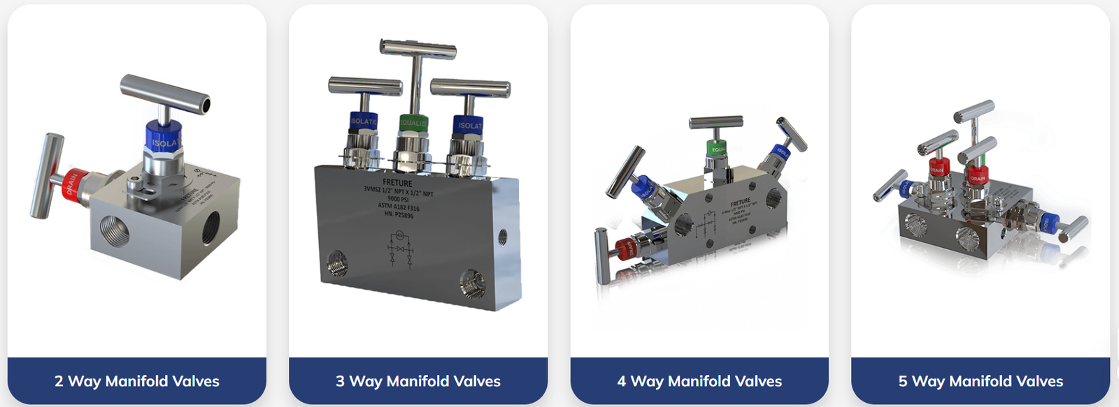
Instrumentation manifold valves sit between a process line and a pressure or differential-pressure transmitter, combining several isolation, equalizing, and vent functions into one compact assembly. Rather than piping individual valves together with tubing and fittings, plants use this valve arrangement to reduce leak points, simplify calibration, and give operators a repeatable sequence for taking a transmitter offline without depressurizing the whole line.
Two-Valve Manifolds
A two-valve manifold provides basic isolation for a single-port instrument such as a gauge pressure or absolute pressure transmitter. Each valve isolates one process connection, allowing the instrument to be removed for service while the line stays under pressure elsewhere. This is the simplest configuration and is common on utility and balance-of-plant pressure points where differential measurement is not required.
Three-Valve Manifolds
Three-valve manifolds are built for differential-pressure transmitters, which measure the difference between a high-side and low-side connection, most often to infer flow through an orifice plate or level in a closed vessel. Two isolation valves shut off the high and low process connections, while a center equalizing valve connects the two sides together. Opening the equalizing valve before closing either isolation valve prevents an overpressure spike on one side of the diaphragm, which is the standard sequence for safely removing a differential-pressure transmitter from service.
Five-Valve Manifolds
Five-valve manifolds add two vent or bleed valves to the three-valve arrangement, one on each side of the isolation valves. These vent valves let technicians bleed trapped process fluid or gas from the manifold cavity before disconnecting the instrument, and they also provide a controlled way to introduce a known test pressure during calibration without removing the transmitter from the process connection. Five-valve manifolds are the standard choice in hydrocarbon processing and other services where venting to a closed system, rather than to atmosphere, is required for safety or environmental compliance.
Direct Mount vs. Remote Mount
Direct mount manifolds bolt straight onto the transmitter flange, eliminating impulse tubing between the manifold and the instrument and reducing the number of joints that could leak or trap air. Remote mount manifolds connect through impulse lines to a transmitter located away from the process connection, which is preferable when vibration, high temperature, or limited access at the tap point make direct mounting impractical. The choice affects not only installation but also response time, since longer impulse lines introduce lag into fast-changing flow or pressure signals. On new construction, direct mount instrumentation manifold valves are generally preferred wherever the tap point allows it, since fewer joints translate directly into fewer potential leak paths over the life of the installation.
Materials and Pressure Ratings
Manifold bodies are commonly machined from 316 stainless steel bar stock, with alloy options such as Hastelloy or Monel specified for corrosive or high-chloride service. Pressure ratings typically range from moderate process duty up to several thousand psi, and the manifold rating must meet or exceed both the transmitter's rated working pressure and the maximum credible line pressure, including any water-hammer or surge conditions. Packing and seat materials also need to be checked against the process fluid separately from the pressure rating, since a valve can be mechanically rated for the pressure while still being chemically incompatible with the fluid.
Calibration and Zero-Checking
One of the main reasons plants standardize on this configuration is the ability to zero-check and calibrate a transmitter without breaking any process connections. With the isolation valves closed and the equalizing valve open, both sides of the transmitter see the same pressure, allowing technicians to confirm the zero reading before returning the instrument to service. This procedure, performed consistently and documented as part of a calibration program, is one of the more reliable ways to catch transmitter drift before it affects process control or custody-transfer measurement.
Common Applications
Differential-pressure manifolds are most closely associated with orifice-plate and venturi flow measurement, where the pressure drop across a restriction is converted into a flow rate, but the same three-valve and five-valve arrangements also support closed-tank level measurement, where the differential reading corresponds to liquid head rather than flow. Custody-transfer applications, such as natural gas metering, place particularly tight tolerances on manifold leak-tightness and valve seat integrity, since even a small internal leak past a closed isolation valve can bias the flow calculation without producing an obvious alarm. For these applications, manifold valves are often specified with a documented leak test as part of factory acceptance, in addition to the pressure rating.
Conclusion
Instrumentation manifold valves give plants a compact, low-leak way to isolate, equalize, and calibrate pressure and differential-pressure instruments without shutting down the process line. Choosing between two-valve, three-valve, and five-valve configurations, and between direct and remote mounting, depends on the measurement type, the venting requirements, and the physical conditions at the tap point. Specifying manifold materials and pressure ratings against actual operating and upset conditions, not just nominal line pressure, remains the most common gap between paper specification and field performance. As with other instrumentation valves for process industries, getting this specification right up front is far cheaper than reworking it in the field.

 Arabic
 French
 Spanish
 Portuguese
 Deutsch
 Turkish
 Dutch
Dutch
 Italiano
 Russian
 Romaian
 Portuguese (Brazil)
 Tiếng Việt